Context
This article details the SMAA implementation in the Vireo RHI Samples examples of the Vireo Rendering Hardware Interface project.
What is SMAA?
Anti-aliasing is one of the fundamental challenges of real-time rendering. SMAA (Subpixel Morphological Anti-Aliasing) offers a post-process approach that operates on the final rendered result: the image is processed after rendering, without using geometry (as MSAA does).
The principle is morphological: the shape of edges is detected to derive adaptive blending weights, which provides quality close to 4× MSAA at a much lower cost.
In this example, SMAA is integrated into the PostProcessing module alongside
FXAA and TAA.
Its implementation is broken down into three compute shader passes, implemented in C++23 and Slang.
Compared to a full-screen quad approach in the graphics pipeline, the compute
implementation avoids beginRendering/endRendering passes and intermediate
render targets: the outputs of each pass are read/write images
(createReadWriteImage) accessed directly
via READWRITE_IMAGE descriptors.
The SMAA Pipeline
SMAA requires three passes to reach the final result:
Each pass is a compute shader dispatching a grid of work groups covering the entire image (groups of 8×8 threads). The shaders are written in Slang, a modern shading language compiled to SPIR-V (Vulkan) or DXIL (DirectX 12).
Unlike the full-screen quad approach in the graphics pipeline, no
vertex shader or vertex buffer is required.
Intermediate buffers are read/write images
(createReadWriteImage) rather than render targets, which
eliminates RENDER_TARGET_COLOR transitions and
beginRendering/endRendering calls.
Pass 1 — Edge Detection
This pass receives the color image output from the rendering pipeline (inputImage)
and produces an image encoding the intensity of horizontal and vertical edges for each pixel.
The compute shader is dispatched with groups of 8×8 threads, each thread processing one pixel.
#include "postprocess.inc.slang"

ConstantBuffer<Params> params       : register(b0);
Texture2D        inputImage         : register(t1);
RWTexture2D<float4> edgeOutput      : register(u2);
SamplerState     sampler            : register(SAMPLER_LINEAR_EDGE, space1);

[numthreads(8, 8, 1)]
void computeMain(uint3 dispatchId : SV_DispatchThreadID) {
    float2 uv = (dispatchId.xy + 0.5) / params.imageSize;

    // Coefficients from the ITU-R BT.601 perceptual luminance formula
    float3 lumaWeight = float3(0.299, 0.587, 0.114);

    // Sampling of the central pixel and its 4 direct neighbors
    float lumaC = dot(inputImage.Sample(sampler, uv).rgb,                            lumaWeight);
    float lumaN = dot(inputImage.Sample(sampler, uv + float2( 0, -1) / params.imageSize).rgb, lumaWeight);
    float lumaS = dot(inputImage.Sample(sampler, uv + float2( 0,  1) / params.imageSize).rgb, lumaWeight);
    float lumaW = dot(inputImage.Sample(sampler, uv + float2(-1,  0) / params.imageSize).rgb, lumaWeight);
    float lumaE = dot(inputImage.Sample(sampler, uv + float2( 1,  0) / params.imageSize).rgb, lumaWeight);

    // Horizontal gradient: left-center difference + center-right difference
    float edgeH = abs(lumaW - lumaC) + abs(lumaC - lumaE);
    // Vertical gradient:   top-center difference  + center-bottom difference
    float edgeV = abs(lumaN - lumaC) + abs(lumaC - lumaS);

    // Direct write: R = horizontal edge, G = vertical edge
    edgeOutput[dispatchId.xy] = float4(edgeH, edgeV, 0, 0);
}
Compared to a fragment shader, the compute shader receives its pixel position
via SV_DispatchThreadID and writes directly into
RWTexture2D via edgeOutput[dispatchId.xy],
without going through a render target or a color attachment.
UV coordinates are reconstructed by dividing by params.imageSize.
Working in luminance rather than RGB offers two advantages:
fewer samples are needed (a scalar instead of a 3-float vector)
and better correlation with human perception.
The coefficients (0.299, 0.587, 0.114) come from the
BT.601 standard, which is standard in computer graphics.
The sampler used here is SAMPLER_LINEAR_EDGE
(addressing mode clamp-to-edge, bilinear filtering).
This ensures that pixels at image borders do not read out-of-bounds texels.
The output image smaaEdgeImage is allocated as
R16G16_SFLOAT, i.e. two 16-bit channels.
The Red channel is used for the horizontal gradient and
the Green channel for the vertical gradient.
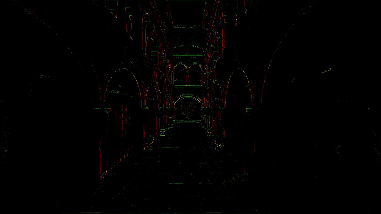
Edge Detection example (Lysa Engine)
Pass 2 — Blending Weight Calculation
This pass consumes the image produced in pass 1 and
calculates a scalar blending weight for each pixel.
It reads edgeImage via a Texture2D
(read-only access) and writes the result into blendOutput,
a RWTexture2D.
#include "postprocess.inc.slang"

ConstantBuffer<Params> params     : register(b0);
Texture2D        edgeImage        : register(t1);
RWTexture2D<float4> blendOutput  : register(u2);

[numthreads(8, 8, 1)]
void computeMain(uint3 dispatchId : SV_DispatchThreadID) {
    // Read H and V edges from pass 1 (integer coordinates)
    float2 edge = edgeImage[dispatchId.xy].rg;

    // The weight is the maximum of the two directions, clamped to [0, 1]
    float weight = saturate(max(edge.r, edge.g));

    blendOutput[dispatchId.xy] = float4(weight, weight, weight, 0);
}
max(edgeH, edgeV) selects the dominant direction
of the edge.
A pixel located at the intersection of a strong edge
in both directions will receive a maximum weight,
which is the desired behavior since this pixel
will benefit more from smoothing.
The saturate(x) function is the GPU equivalent of
the C++ function clamp(x, 0, 1).
Unlike pass 1, no sampler is used here:
edgeImage[dispatchId.xy] performs a direct access by integer coordinates
(equivalent to nearest-neighbor without filtering),
which is exact since edge data is read pixel by pixel.
Out-of-bounds accesses return zero thanks to the default behavior
of Texture2D in border mode.
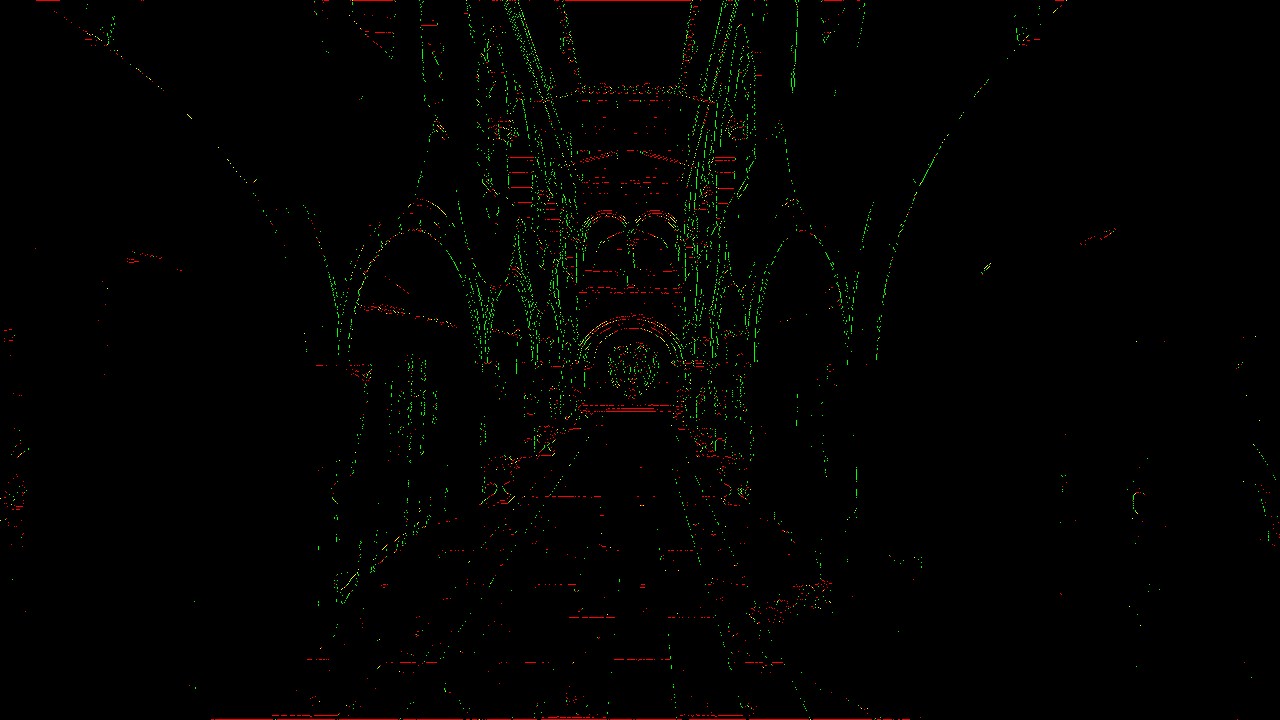
Blending Weight example de mélange (Lysa Engine)
Pass 3 — Neighborhood Blending
The final pass combines the original image with its immediate neighbors, proportionally to the weights calculated in pass 2.
#include "postprocess.inc.slang"

ConstantBuffer<Params> params      : register(b0);
Texture2D        inputImage       : register(t1);
Texture2D        blendBuffer      : register(t2);  // Output from pass 2
SamplerState     sampler          : register(SAMPLER_NEAREST_BORDER, space1);

float4 fragmentMain(VertexOutput input) : SV_TARGET {
    float4 color = inputImage.Sample(sampler, input.uv);      // Central pixel
    float2 blend = blendBuffer.Sample(sampler, input.uv).rg;  // H and V weights

    float4 n = inputImage.Sample(sampler, input.uv + float2( 0, -1) / params.imageSize);
    float4 e = inputImage.Sample(sampler, input.uv + float2( 1,  0) / params.imageSize);

    // Vertical interpolation: blend with North neighbor
    float4 blended = lerp(color, n, blend.r);
    // Horizontal interpolation: blend with East neighbor
    blended = lerp(blended, e, blend.g);

    return blended;
}
This pass is the only one to use the
smaaDescriptorLayout layout with three bindings:
the parameters buffer (b0),
the original color image (t1),
and the weight buffer (t2).
The first interpolation (lerp)
blends the current pixel with its North neighbor
proportionally to blend.r
(horizontal edge detected = top/bottom transition).
The second blends the result with the East neighbor according to
blend.g.
Where there is no edge (blend ≈ 0),
the pixel is returned unchanged.
Where a strong edge is detected (blend ≈ 1),
the pixel is heavily interpolated with its neighbor in the
direction perpendicular to the edge.
Integration into the PostProcessing Pipeline
The samples.common.postprocessing module (PostProcessing.ixx and PostProcessing.cpp)
manages the entire lifecycle of the post-processing passes.
Pipeline initialization (onInit)
// Creation of the three SMAA graphics pipelines
pipelineConfig.colorRenderFormats.push_back(vireo::ImageFormat::R16G16_SFLOAT);
pipelineConfig.resources = resources;  // standard layout (2 bindings)

pipelineConfig.fragmentShader = vireo->createShaderModule("shaders/smaa_edge_detect.frag");
smaaEdgePipeline = vireo->createGraphicPipeline(pipelineConfig);

pipelineConfig.fragmentShader = vireo->createShaderModule("shaders/smaa_blend_weigth.frag");
smaaBlendWeightPipeline = vireo->createGraphicPipeline(pipelineConfig);

// Pass 3 has a different format and layout
pipelineConfig.colorRenderFormats[0] = renderFormat;   // final image format
pipelineConfig.resources = smaaResources;               // layout with 3 bindings
pipelineConfig.fragmentShader = vireo->createShaderModule("shaders/smaa_neighborhood_blend.frag");
smaaBlendPipeline = vireo->createGraphicPipeline(pipelineConfig);
Two different descriptor layouts are created: descriptorLayout (2 bindings: params + input) for passes 1 and 2, and smaaDescriptorLayout (3 bindings: params + input + blendBuffer) for pass 3.
Render loop (onRender)
The SMAA pass in onRender is integrated alongside the other
post-processing passes:
// === Pass 1: edge detection ===
cmdList->barrier(colorInput,          // source image → shader read
    vireo::ResourceState::RENDER_TARGET_COLOR,
    vireo::ResourceState::SHADER_READ);
cmdList->barrier(frame.smaaEdgeBuffer,  // edge buffer → render target
    vireo::ResourceState::UNDEFINED,
    vireo::ResourceState::RENDER_TARGET_COLOR);
frame.smaaEdgeDescriptorSet->update(BINDING_INPUT, colorInput->getImage());
// ... beginRendering → bindPipeline → draw(3) → endRendering

// === Pass 2: blending weights ===
cmdList->barrier(frame.smaaEdgeBuffer,  // edge buffer → shader read
    vireo::ResourceState::RENDER_TARGET_COLOR,
    vireo::ResourceState::SHADER_READ);
cmdList->barrier(frame.smaaBlendBuffer, // blend buffer → render target
    vireo::ResourceState::UNDEFINED,
    vireo::ResourceState::RENDER_TARGET_COLOR);
frame.smaaBlendWeightDescriptorSet->update(BINDING_INPUT, frame.smaaEdgeBuffer->getImage());
// ... beginRendering → bindPipeline → draw(3) → endRendering

// === Pass 3: neighborhood blending ===
cmdList->barrier(frame.smaaBlendBuffer, // blend buffer → shader read
    vireo::ResourceState::RENDER_TARGET_COLOR,
    vireo::ResourceState::SHADER_READ);
frame.smaaBlendDescriptorSet->update(BINDING_INPUT,      colorInput->getImage());
frame.smaaBlendDescriptorSet->update(BINDING_SMAA_INPUT, frame.smaaBlendBuffer->getImage());
// ... beginRendering → bindPipeline → draw(3) → endRendering
The pattern is identical for each pass:
barrier on the source (transition to SHADER_READ),
barrier on the destination (transition to RENDER_TARGET_COLOR),
descriptor set update, then draw execution.
Barriers ensure correct GPU synchronization between
passes (making sure data is fully written into buffers before being read).
SMAA vs FXAA vs MSAA — Comparison
The Vireo RHI examples in this project integrate three anti-aliasing techniques:
FXAA (Fast Approximate Anti-Aliasing)
FXAA detects edges via local contrast and applies a directional blur in a single pass. Extremely fast, but may make the image slightly blurry, especially on textures.
SMAA (Subpixel Morphological AA)
SMAA analyzes edge morphology to produce more accurate blending weights. Quality is superior to FXAA, with less sharpness loss. The cost is higher (3 passes) but remains very acceptable on modern hardware.
TAA (Temporal Anti-Aliasing)
TAA exploits the history of previous frames to accumulate more information. Excellent quality on static geometry, but requires a velocity buffer and ghosting management for fast-moving objects.
The TAA + SMAA combination (supported in this example) is particularly interesting: TAA stabilizes the image temporally while SMAA refines spatial edges, each compensating for the other's weaknesses.
Conclusion
Several improvement directions are possible to get closer to "full" SMAA:
- Use an edge search LUT in pass 2 to compute precise directional weights based on edge length
- Implement stencil masking to process only pixels near an edge, reducing GPU load
- Add the SMAA T2× variant (with temporal jitter) for even finer subpixel anti-aliasing